
... further steps
in 2022
... two and two
the first wheels
MT18, wheel in wheel
MT18 with two arms
MT18 with three arms
Sketch of wheel 1
AP wheel in 3D
back to next steps
back to startpage
| back to german |

© 2022 by Alois Zimmermann | Kontakt | Impressum | Updates | Ausblick |
Time to present the first construction plan
Little is known of Bessler's first wheel, which he presented to the public in Gera on June 6, 1712, only the diameter of about 5 feet (DT 107). A little more is passed down of the second wheel of Draschwitz. According to Bessler, this one was built like the first one (DT 18), only larger, with 5 ells, twice as large in diameter.
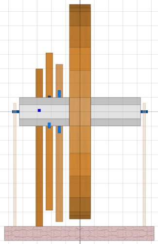 |
So here in the picture the first wheel is shown with a diameter of about 150 cm.
In addition the report of Gottfried Teuber (1656 - 1731), court deacon
and Magister in Zeitz, who describes in it the second wheel of Bessler,
the Draschwitz wheel from 1714: „It is a hollow wheel of wood, ten feet in diameter and six inches thick. It is covered by thin wooden planks to hide the internal mechanism. The axle is also made of wood and extends one foot beyond the wheel on both sides. It has teeth which are for moving three stamping timbers, similar to those found in tamping mills. These stamps are quite heavy, and they are lifted and dropped continously. The iron axle journals rotate in open bearings, so that one can exclude a fraud by external energy supply. I had arranged a meeting with the inventor. As we approached the machine, I could see that the wheel was locked with a thick rope. As soon as the rope was released, the machine began to turn with great force. For a long time it neither accelerated nor slowed down its speed. To stop it again required great force.” The image has a grid of 10 cm. The thickness of the wheel is about 16 cm, the axle has a diameter of about 20 cm and the stamping timbers are each about 5 cm wide. |
The outer appearance of the wheel is thus fixed, now it is time for the „innards”,
as Bessler calls it on the first pages of his Apologische Poësie:
„Its innards gain weight/
Otherwise no preponderance comes along/”
Known and new principles have to be cleverly combined here.
1) The unbalance generation with the scissor mechanism similar to the earlier page
„Wenn ein Pfund ..”;
2) the excitation by „centrifugal force-free” weights in the axle,
which according to MT34, MT69 (and also MT40) provide a suitable preload;
3) the stamper pulses introduced at the right place, which trigger the swing-in and swing-out processes
and bring them to a safe completion;
and 4) the MT18 springs at the swing-out flying weights.
|
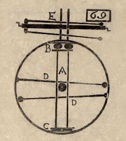
To understand the mechanics inside the axle, let's first look at MT69 again.
For me, 3 aspects are interesting here: First, the levers that rest inside the axle,
with weights at the ends. Then the representation how the small deflections of the levers D
in the wheel create an unbalance and thirdly the notation of the number 69. The levers D
in the wheel actually make little sense, considering the centrifugal force,
their reaction to the unbalance displacement would simply come too late.
However, if one assumes that the levers D are identical with the levers E,
which lie centrifugally-free in the axle, then suddenly everything is clear.
The weights at the ends of the levers E are so heavy, that they can generate the unbalance.
And a start impulse, approximately at the point where the „E” is,
could trigger the movement at the right time (keyword camshaft). (Bessler likes to do that, that he brings the not visible 3rd dimension by a 90 degree rotation into the 2-dimensional sketch). Now it also becomes clear how MT40 is to be interpreted. MT40 shows the connection of the scissors mechanism to the levers in the axle. |
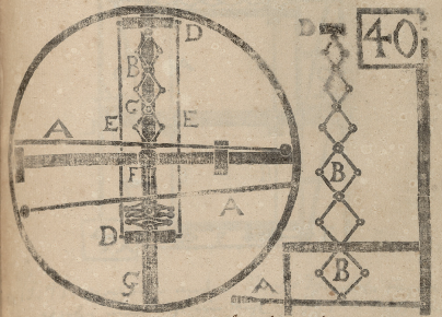
|
As with MT69, you should imagine the levers A lying in the axle.
The scissor has its fixed point at the wheel in C.
If in the upper part of the picture the scissor link is pulled downwards by lever A,
the weight D is moved upwards by the upper scissors links. Very interesting are the two small rectangles on the horizontal spoke of the wheel. The obvious interpretation is, of course, that a second system is working here, shifted by 90 degrees. Then the wheel would turn ccw - also interesting. In the right rectangle i however assume a small hint of the point of attack of a stamper impuls. And this brings us to the next picture, the technical implementation in a wheel with three stampers. |
And that's where the display problems start:
Compared to the actual wheel, the dimensions of the mechanics in the axle are tiny.
Hence the zoom out in the following pictures.
Also the ratios of the forces are impressive.
For me, Bessler is „the man of the crazy ratios”.
And maybe this is his secret.
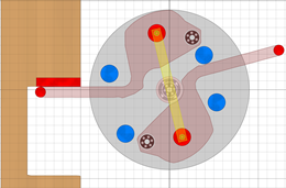
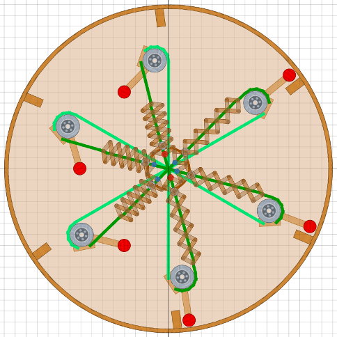
Here, finally, the big picture: Each stamper operates one peg mechanism,
that is, two pegs to manage two scissors.
Bessler's art was to house all of this into the axle.
He could not simply increase the diameter, because otherwise
too much energy would be needed to lift the stamper.
There are 6 levers in the axle (levers E according to MT69),
two red (currently active) and four blue.
The remaining gaps must accommodate the mechanics of the pegs.
When the wheel turns clockwise and the stamper still holds down the peg,
the upper red point is pressed down (=inward) by approx. 10 mm.
Zapfenmechanik vergrößert:
 Anfang Stampferhebung
|
|
|---|---|
 Ende Stampferhebung
ca.60 Grad Raddrehung pro Eingriff |
|
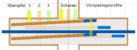
Inside the axle we see a through-going shaft with the axle journals at the ends, which rotate in the outer bearings (open cups only at Bessler) and six solid levers, which transmit the stamper impulses to the sissors and which each have heavy weights at the ends. |
The deflection of 10 mm at the stamper (e.g. yellow arrow 1)
is already more than 20 mm at the attachment point of the scissors mechanism
(yellow arrow in the center of the wheel) and the sissor makes it to approx. 10 cm.
This is sufficient for swinging the flying weights in and out (according to MT138).
So that the two levers E go down in parallel, there is a coupling of the two
(yellow link), it is located at the heavy weights, the preload weights
(„Vorspanngewichte” in german).
The preload weights must be so heavy that they could perform the swinging in and out
of the flying weights almost alone. They pretension the scissors just enough,
that nothing moves yet, but that it can then move very quickly and with little energy,
when the stamper intervenes.
The arrows show where the stampers engage and where the sissors attach.
Because of the small thickness of the wheel, the distances cannot be exactly
the same for the three systems. Perhaps this is the reason that the wheel did not
run completely round (possibly as in three-quarter time).
And now we also understand Bessler's verse in PA 29/30:
„as soon as you have realized/
That my shaft is not that way/
But/ it rather has many pockets/
Yes through and through different holes.”
The shaft was probably not the same thickness and round everywhere,
probably thicker inside, but had recesses here and there where the
preload weights rested in and holes there, where the six ropes
and the connections of the preload weights passed through.

|
And now briefly to the number 69 in MT69 (see above): As described earlier: 6 + 9 = 15 - an interesting aspect. But also the notation is somehow special. I have once swapped 6 and 9 --- and i see there the inner peg mechanism. |
Now that the simple simulation programs have reached their limits, the only thing left for us to do is to build a prototype. In principle, everything is outlined and the reproduction of the Gera wheel can begin.
In addition, a few aids:
- the speed of the wheel should be between 40 and 50 rpm
- the weight of a stamper is probably between 6 and 10 kg
- a flying weight could have about 0.5 to 1.0 kg
- the spring on the flying weight (MT18) must match the speed (spring constant/time constant)
- second flying weights could improve the starting characteristics and the power of the wheel
(Second flying weights could be installed between the main flying weights.
They are smaller and are pulled by the main flyweights with a delay,
so the unbalance would be generated by 12 masses)
- last but not least, the energy of the falling tampers should be recovered.