
... further steps
in 2022
... two and two
the first wheels
MT18, wheel in wheel
MT18 with two arms
MT18 with three arms
Sketch of wheel 1
AP wheel in 3D
back to next steps
back to startpage
| back to german |

© 2023 by Alois Zimmermann | Kontakt | Impressum | Updates | Ausblick |
Motus in 3D, the new interpretation of the AP wheel
Behind the graphic at the end of Besslers book Poëtische Apologie,
which up to now I have called Motus, actually nothing less is
hidden than the core mechanism of the two large bidirectional wheels.
You only have to look at it in 3D. Who still wants to call Bessler a cheat
and to deny his genius as an inventor of self-running machines?
But one point after the other:
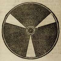 |
The picture on the left is the original from the book Poëtische Apologie. The picture on the right is the top view of a construction with Blender. The two full circles in the original will be explained later, because this would reduce the clarity for the time being. |
 |
If you now rotate the Blender construction out of the top view, you will get the image below.
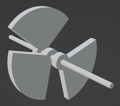 |
On the shaft of the Bessler wheel are turning the segments of friction wheels on three planes and each rotated by 120 degrees. The segments probably consisted of a material very similar to todays hard rubber. They had to withstand high forces and also be able to spring back. (A composite with leather?) |
The next picture shows the beginning of the lifting process of one plane:
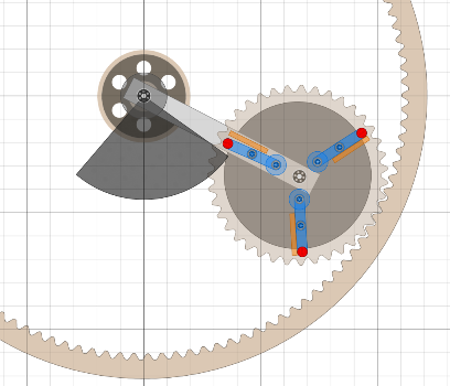 |
The friction wheel segment is just taking hold with the unbalance wheel with the flying weights on it. The greatest acceleration would be experienced by the flying weight near the axle. Since the spring absorbs the initial impulse, both the force and the wear are reduced. The speed of the Motus unit is approx. 9 to 12 times as high as the speed of the wheel. And as Bessler writes in MT13: „... or someone would be present who would lift the weight (above at D) always like lightning.” |
And now we come back to the two circles in the original AP picture.
They probably represent the driving gear and at the same time
a flywheel too of this Motus unit. For a correct function the speed needs
to be at least 9 times the speed of the wheel - thus a flywheel makes sense.
This can explain both the run-up during the starting process and the high
torque when braking the wheel.
With a factor of 9, there should be practically no slippage and also
the run-up would hardly work. I believe that the speed was higher by
a factor of 12 and that Bessler compensated the slipping and the regular
overstroke somehow. So there were about 8 strokes per wheel revolution
(controlled by the tampers).
|
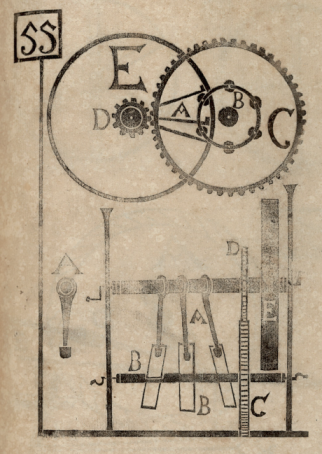
And MT55 again reveals some small information: The wheel of the letter E is a flywheel. Because of the six pivots (three tampers), I have assigned MT55 to the first wheels so far. But gear and flywheel speak well for the two big wheels. Even though there are four tampers on the big wheels, I am convinced now, that there have been three planes inside. In addition another small preview now: On the big wheels, the axle side with the pivots was not directly connected to the wheel. It could have a slightly different speed. If the wheel ran backwards then the axle even continued to run in the usual direction. It only could rotate in one direction, otherwise the tamping mechanism would have blocked. It will be another hard nut to crack to decipher all these mechanics. One thing however is for sure: Bessler knew well about gears and somehow he managed to do it. |